1. THE RARE EARTH ELEMENTS
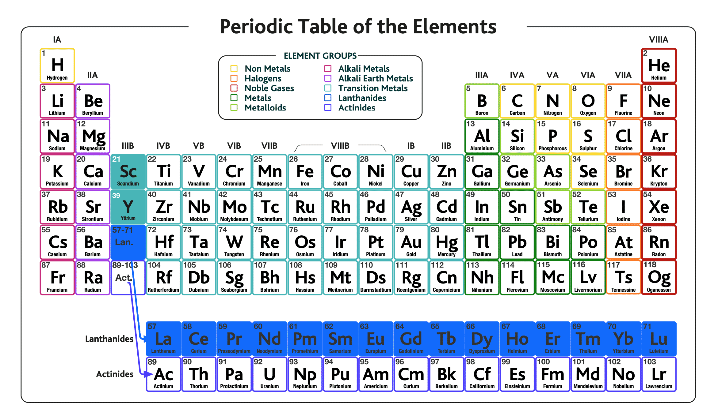
Figure 1. Periodic Table of the Elements
In the periodic table of the elements, rare earth elements (REEs) are the group of elements in the row labelled “lanthanides” and are highlighted in blue, but also include yttrium (Y) and scandium (Sc) because these elements possess similar chemical characteristics.
1.1 Natural abundance of REEs
Although almost all elements on the periodic table are present in the Earth’s crust (the outer rocky layer of the Earth), their absolute abundances are very variable, as this graphic below from the United States Geological Survey demonstrates. It plots the abundance of each element per one million atoms of silicon:
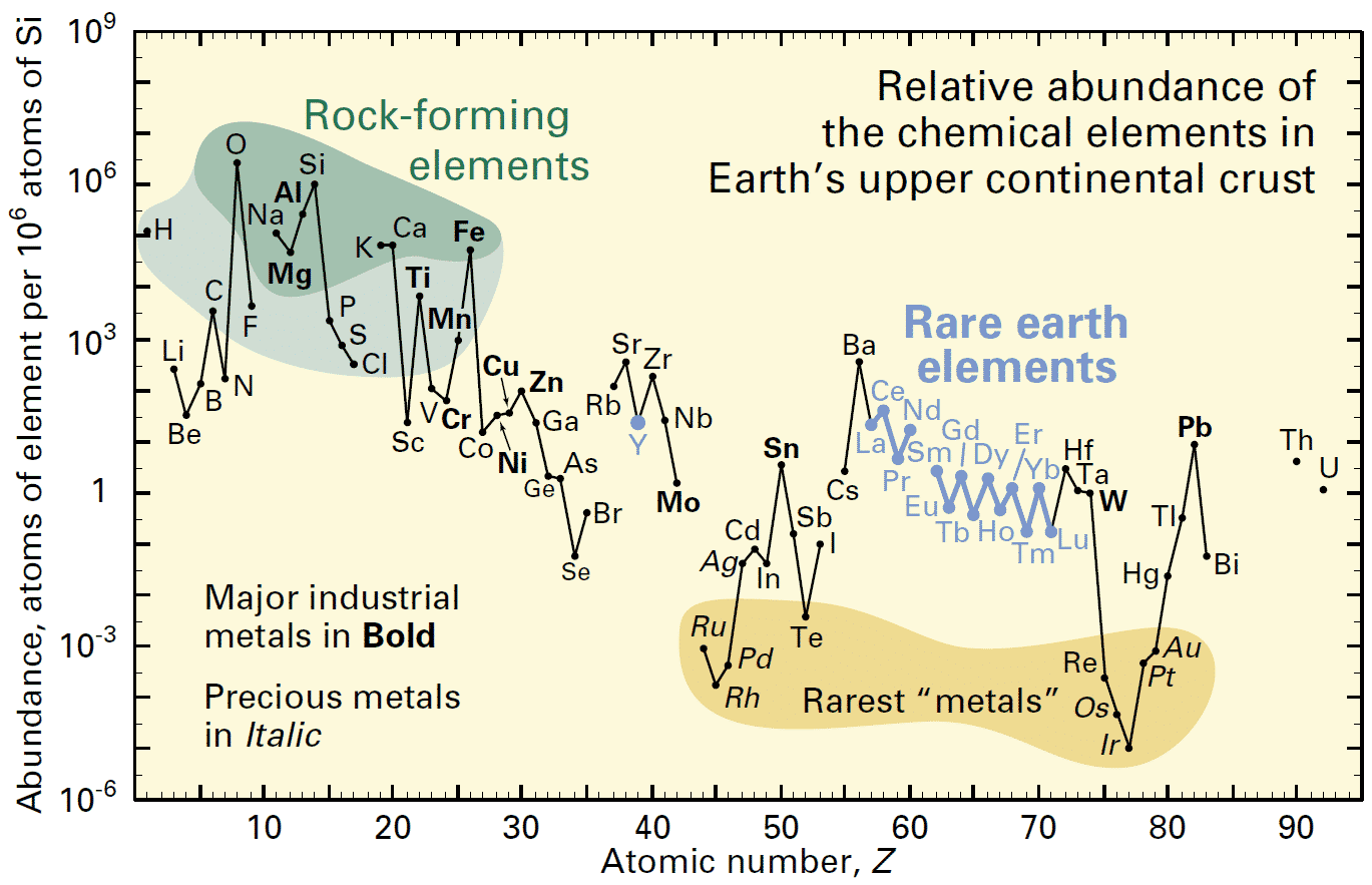
Figure 2. Relative abundance. How rare is rare?
We can see that some metals, with names that are familiar, such as aluminium (Al), iron (Fe) and copper (Cu) are relatively abundant. Many of the elements that facilitate our modern technologies like the rare earth elements (La thru Lu) are less abundant but still not necessarily really that “rare”, similar in crustal abundance as tin (Sn), for example. They are certainly not as rare as the precious metals that we are most familiar with, such as gold (Au). It is the concentration of these elements by natural geological processes that determines if and where they occur in sufficiently concentrated forms and in accessible enough locations to become an economically viable and environmentally acceptable working mine.
1.3 REEs and metal demand over time
We have been using metals for thousands of years. While we use large quantities of some metals, such as iron, aluminium and copper, we use smaller amounts of other metals, such as palladium, platinum and scandium, as shown in the graph below.
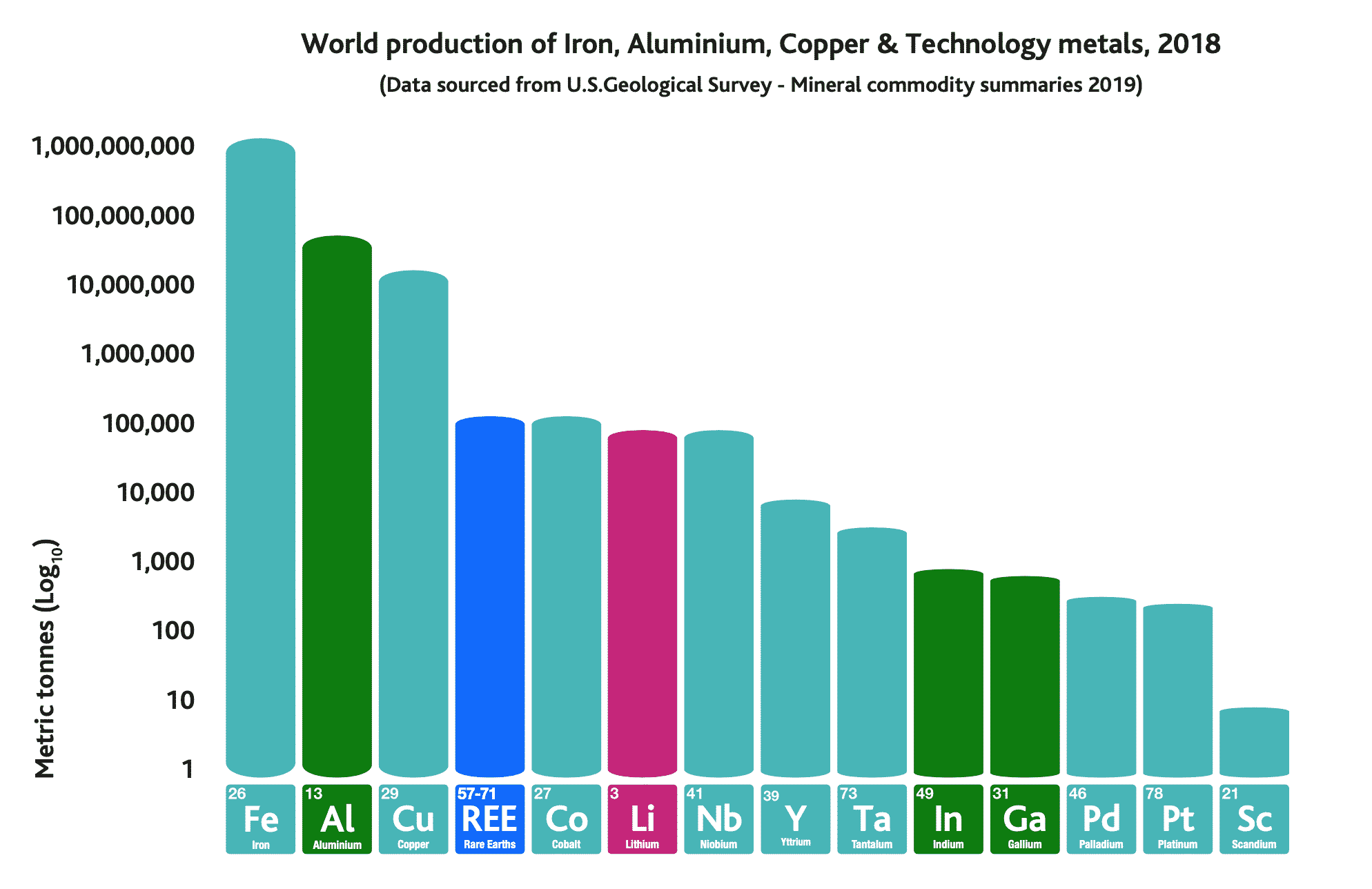
Figure 3. World production in 2018 comparison between well-known metals and specialty/rare metals.
World production of iron, aluminium, copper and technology metals in 2018. Note that the y-axis (metric tonnes) is on a logarithmic scale, so each step on the axis is 10 times more than the previous step.
REE production amounts to c.130,000 tonnes in 2018.
REE production is largely made up of the REE elements cerium, lanthanum, neodymium, praseodymium, dysprosium (the other REEs are only used in small amounts).
However, today we are using not just larger amounts of raw materials but also more elements from the periodic table. This is particularly so for technology metals.
This can be illustrated nicely below in Figure 4 by thinking about how energy has been generated. Think back to the 1700’s, with wood, coal, and devices such as windmills built of stone, lime and iron. In the industrial revolution the number of materials widened, with copper, manganese and lead in wood- and coal-fired steam engines and then a wider range of elements again as oil and gas took over from coal and cars and other powered devices became more complex.
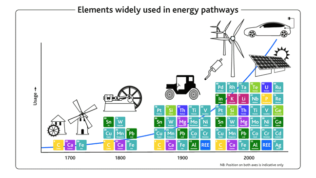
Figure 4. Schematic graph showing elements used in technology over time.
Today, in the age of digital technologies and renewable energy, the number of elements (metals and non-metals) with important industrial applications has grown to cover almost the entire Periodic Table. For example, solar panels (cadmium, tellurium, selenium, indium, gallium), wind turbines and electric cars (neodymium, praseodymium, dysprosium) and catalytic converters in conventional cars (platinum, lanthanum, cerium) are examples of devices that use the more unusual metals because of their unique functional properties. Electric vehicles will maintain, and indeed increase, the need for this diverse array of raw materials, and REEs are a vital part of that.
2. REE DEPOSIT TYPES

Figure 5. Schematic graph showing elements used in technology over time. Schematic from Rare Earth Elements: Minerals, Mines, Magnets – Chakhmouradian & Wall. Elements Magazine, Volume 8, Number 5, October 2012
As mentioned before REEs are not particularly “rare” in the Earth’s crust but economic accumulations of them are rare. The “all-in-one” diagram in Figure 5 above shows all of the different REE deposit types. You don’t need to be a geologist to fully understand this diagram, but you can see that REEs occur in a vast array of geological environments. Some are intruded into the Earth’s crust from depth and regarded as “primary”, whilst others have been subject to chemical and physical weathering and can be described as “secondary”.
The diagram above is overly detailed, but let us just focus on the most important deposit types:
2.1 The main economic REE deposit types – an overview
- Mineral Sands
- Carbonatites
- Alkaline rocks
- Ion adsorption clays
MINERAL SANDS
- Reasonably large deposits
- But relatively low-grade in REE
- The REE minerals (monazite and xenotime) are by-products of larger Ti, Zr minerals (ilmenite and zircon) mining
- Easy to mine as little blasting and milling required
- High-radioactivity because they are derived from thorium (Th) and uranium (U) bearing weathered granites and metamorphic rocks
- Example deposit: IREL Mineral Sands India
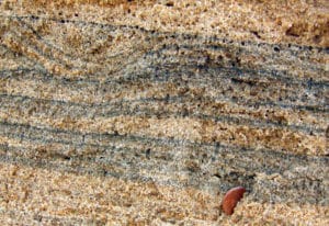
Figure 6. A mineral sand aka “placer” deposit for zircon, titanium and by-product REE minerals
CARBONATITES
- Reasonably large deposits
- Higher REE grade
- Fresh “primary” un-weathered carbonatites – large grain size
- Secondary weathered carbonatites – fine grain size with variable radioactivity
- Usually “light” REE (aka LREEs) enriched i.e., Ce, La, Nd, Pr
- Example deposits: Primary carbonatite: Mountain Pass, USA. Secondary carbonatite: Mount Weld, Australia
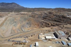
Figure 7. An open-cut primary carbonatite REE mine.
ALKALINE ROCKS
- Large deposits
- Lower REE grade
- Hard rock requiring high energy to blast and mill
- Complex mineralogy – weird and wonderful minerals like eudialyte are challenging to process
- Mid-level radioactivity
- Higher amounts “heavy” rare earths (aka HREEs) Y, Dy, Tb.
- Example deposit: Lovozero, Russia
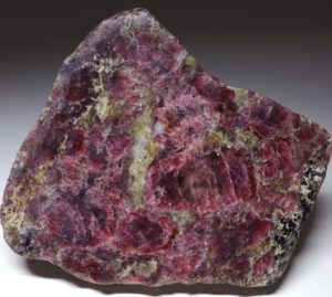
Figure 8. Eudialyte a complex REE bearing silicate mineral found in Alkaline Rocks
ION ADSORPTION
- Small / shallow deposits
- Low REE grade
- Easy to mine as hosted in soft clay
- The REE is “leached” i.e. chemical saturation ‘in situ’ – leads to high environmental impact
- Low radioactivity
- Example deposit: South China Clay Deposits
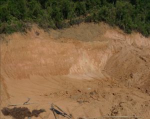
Figure 9. Ion Adsorption clay REE deposit in South China
2.2 REE mining in 2021
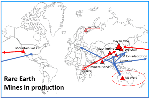
Figure 10. Trade flows of REE mineral concentrates and intermediate REE products. Red triangles are active REE mines in 2021 (NB. Gakara production in Burundi is halted as of August 2021)
The diagram above shows todays REE production centred on a handful of mostly carbonatite hosted deposits, mainly in China showing why this country is the World’s dominant REE producer. Mineral concentrate production in USA and Burundi also goes to China for further processing. Only Mount Weld (Lynas) in Australia, Indian mineral sands and Russia produce and refine REEs outside of China. Mount Weld uses its processing hub in Malaysia for REE refinement of its Australian mineral concentrate. The reasons that only a handful of deposits are in production is down to a range of factors but chief among them is that they are targeting conventional REE ores such as monazite and bastnasite, and they have been proven to be economically extractable.
2.3 REE deposits – what are they and how do they differ?
Let’s focus on 3 of the main REE deposit types in further detail.
- Carbonatites
- Weathered carbonatites
- Mineral sands
1 Carbonatites
Carbonites are a rare type of molten igneous rocks derived from inside the Earth.
Unlike almost all other igneous rocks, like granites for example, they are not made of hard silicates minerals like quartz and feldspar, but of soft carbonate minerals, such as calcite and dolomite, together with accompanying minerals like magnetite and apatite. You may know calcite and dolomite in much more common rocks, e.g. limestone (sedimentary rock type), marble (metamorphic rock type), or limescale build up in your kettle.
Carbonate igneous rocks are so rare that only one volcano in the world, Oldoinyo Lengai in Tanzania, has ever been observed to erupt them.

Figure 11. Oldoinyo Lengai carbonatite volcano, Tanzania. Wikipedia Commons
However, carbonatites are important sources of commodities such as rare earth elements (REE), niobium, tantalum, phosphate, fluorspar and zirconia. Although rare as an igneous rock type, carbonatites are distributed around the world.
Carbonatites chiefly form in the middle of continents, often associated with deep crustal fractures and ‘extensional regimes’ such as rift valleys, where the crust is undergoing stretching. Molten carbonatite magmas originate deep in the Earth’s mantle – sometimes to many kilometres’ depth – similar to kimberlites that host diamonds. Once intruded into the earth’s crust, like a bursting bottle of soda (carbonatites and soda are both powered by carbon dioxide!), carbonatites usually form plug-like intrusions or sheet-like structures called dykes. Carbonatites like to take advantage of structural weaknesses like faults in the crust and are accompanying by adjacent areas of alteration, also usually mineralized as well.
In terms of REE carbonatites contain higher proportions of REE in their magmas than most other rock types. In the final stages of crystallization, REE ore minerals may form direct from carbonatite magma, or more usually from fluids associated with the magma. Typical REE ore-minerals include bastnäsite, synchysite and monazite. Textures in these “primary” carbonatites can vary from fine-grained (microns) to coarse-grained (centimeters); mineral assemblages are either well-endowed with REE minerals or not so – all these factors having implications on economic viability in terms of how “mineable” or “extractable” they are.
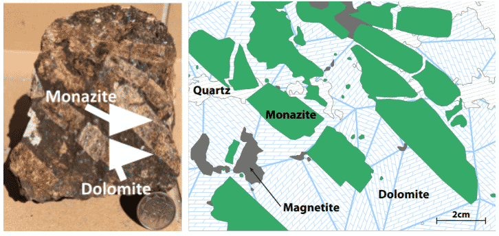
Figure 12: Coarse-grained REE bearing monazite crystals to 50mm (5cm) in length in carbonatite at Eureka, Namibia. Mineral grains of this size are easier to “liberate” from the host rock assemblage.
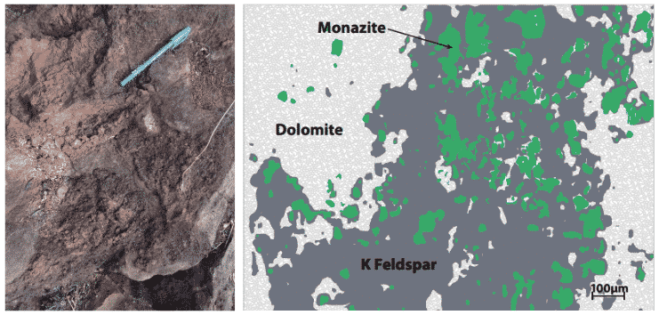
Figure 13. Fine-grained monazite to 200 micron (0.2mm) crystal size in primary carbonatite and “fenite” from a carbonatite in Southern Africa.
Fenite is a type of rock that forms in the host rocks when it is intruded by carbonatite magmas or associated fluids – it is normally characterised by potassium or sodium feldspars (the minerals orthoclase or albite respectively). Apart from monazite, other REE ore-minerals such as bastnasite and synchysite can form in these assemblages. The relatively fine-grained target ore-minerals are a real challenge to extract, or “win”, efficiently from the host rock.
-
Weathered carbonatites
Strong weathering in warm and wet climates will change carbonatites into laterite soils. The easily soluble carbonate minerals in carbonatites dissolve and the most soluble elements get washed away. In fact, most carbonatites have been weathered and altered to a certain degree. However, the less-soluble elements such as REEs can stay in the soil profile, often forming new minerals that are usually very fine grained, for example, secondary monazite, rhabdophane or crandallite-group minerals. The REEs can become concentrated into quite sizeable, easily-workable deposits. However, mineral assemblages vary greatly between weathered carbonatite deposits depending on a) nature of the primary carbonatite, and b) the type and degree of weathering and later hydrothermal alteration it may have experienced. For example, some weathered carbonatites can have low radioactivity in the re-mineralised assemblages, whereas other can concentrate radioactivity in certain minerals.
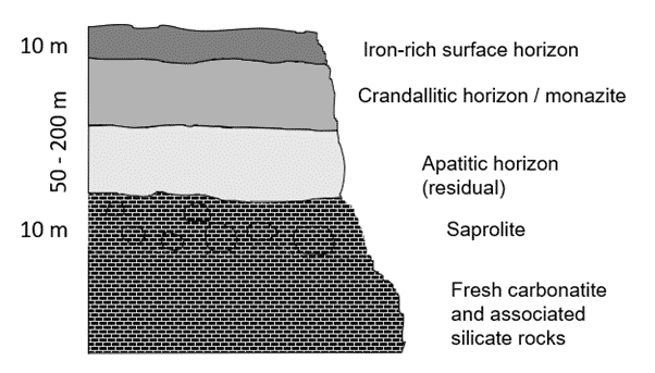
Figure 14. An example of a monazite-bearing laterite profile of a weathered carbonatite.
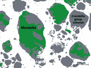
Figure 15. Weathered carbonatites hold fine-grained REE minerals in complex mineral assemblages, often associated with clays such as crandallite. This texture can often cause processing issues because the small target REE-bearing minerals are difficult to liberate from fine grained clays.
-
Mineral sands
REE minerals are not just restricted to carbonatites. Other igneous rocks (originally molten) such as granites, gneisses (metamorphic rock type e.g. heat/pressure altered granites) and sedimentary rocks derived from them, can contain small amounts of REE minerals, such as monazite. When the solid rock is weathered, the monazite grains can be transported away on a long journey down river systems to eventually find their way to the sea. Insoluble minerals that are resistant to wear can survive these long journeys and on reaching the sea may be concentrated on beaches and in river deposits. Most of this material is quartz (sand) but deposition processes can produce concentrations of heavy (i.e. dense) minerals in certain places.
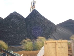
Figure 16. Mineral sands processing mainly for titanium and zirconium minerals with by-product monazite.
These mineral sand deposits are particularly notable as a source of titanium from ‘heavy minerals’ like ilmenite and rutile. Monazite is concentrated in these deposits too and may be mined as a by-product of the titanium minerals. The problem with these REE deposits is that monazite from a granite parent source tends to have higher radioactive Th and U content, up to 10% of the total weight, and this makes the resulting concentrate difficult to transport and process – this is around 20 times higher than many primary carbonatite derived monazites. This is a pity because mineral sands are quite common around the world since granites are more plentiful than carbonatites.
Radioactivity is a something that is inherent to REE deposits. However, the amount of radiation can vary greatly between deposit types – and is related to the “genetics” of the parent deposit, but also dependent on types of weathering and alteration. This can be low-radioactivity which pose very little risk to workers to high-radioactivity where strict management plans need to be emplaced.
A way to compare deposit types is by neodymium to radioactive thorium ratio i.e. how much thorium is there in the target ore mineral vs neodymium. In other words, how many tonnes of thorium is produced for every tonne of neodymium produced.
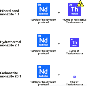
Figure 17. Neodymium:thorium ratios between deposit types compared. How much thorium is generated per tonne of Neodymium produced? As one can see, not all monazites are the same!
2.4 REE minerals mining & processing
Outlined below is a simplified flow sheet for three REE deposit types – from the host minerals in the ground to the mineral concentrates, and subsequently the separation into individual 17 REEs towards the end. None of these processes are easy, and many hurdles need to be overcome along the way. For example, it may seem that “easily leachable” aka ion adsorption clays by-pass a lot of the mining and mineral processing steps – but remember that this REE deposit type is very low grade in comparison, and has marked environmental impact in its extraction – because more ground has to be stripped and treated with chemicals.
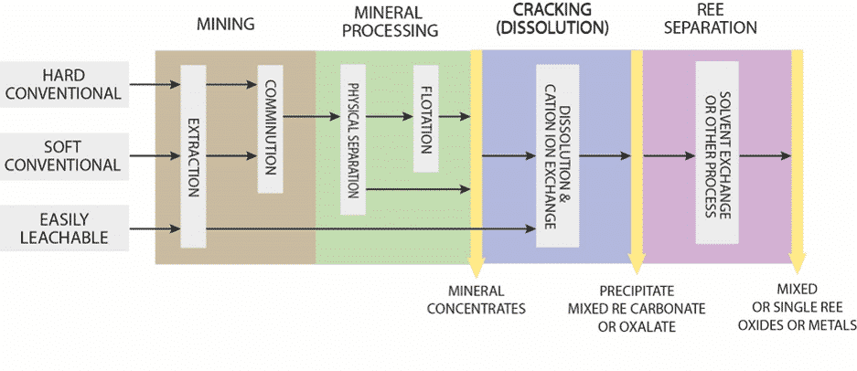
Figure 18. Generalized flow-sheets between REE deposit types.
Let us look at the mining and mineral processing of hard and conventional deposits. Efficient mineral processing of a target ore is what hinders most REE developers new to this sector. There is little future for a large REE resource if the target ore minerals cannot be recovered economically.
MINING AND COMMUNITION
Mining operations extract ore-bearing rock from their open pit or underground operations.
This material being ferried around in big mining trucks, or on railed mine carts, is often referred to as run-of-mine (ROM). The ROM needs further processing to separate the minerals of interest from the host rocks. There are many factors involved in this process, and in fact this area is an engineering subject in its own right, and has various names, including mineral processing, minerals engineering and metallurgy.
In brief, target ore minerals are often tightly bound in their host rocks and mineral processing generally involves three types of operation to liberate and concentrate these target minerals, often referred to as beneficiation:
- comminution
- sizing
- concentration
Comminution is the reduction of the particle size of the materials, involving crushing and grinding the rocks to a smaller size. Crushing is done by jaw crushers, gyratory crushers and cone crushers. Grinding is done by rod mills and ball mills.
Sizing is the separation of target mineral particle sizes by screening or classification.
An important factor in both comminution and sizing operations is the determination of the particle size distribution of the materials being processed, commonly referred to as particle size analysis – i.e. at what size are the target minerals best liberated from the waste minerals.
Concentration of the target mineral, or targeted removal of waste minerals (also known as gangue), takes advantage of the physical and surface chemical properties of the minerals. Find out more about concentration of target minerals in the next step.
Concentration of target minerals requires separation of the ore mineral or minerals from the waste material (aka gangue minerals).
PHYSICAL BENEFICIATION
Gravity separation takes advantage of the difference in specific gravity (density) between minerals and by their relative movement in response to gravity and one or more other forces (such as centrifugal forces, magnetic forces, buoyant forces). Methods utilising these physical difference include: dense media separation (DMS), shaking tables, spiral separators, and multi-gravity separators. Gravity is a preferred method if liberation of the target ore-mineral is determined as “easily liberated” from its host rock mineral assemblage and/or of coarse grain-size, as well as having high density differential to the waste minerals. Gravity separation is one of the more cost-effective mineral processing routes. Gravity concentration of REE ROM from appropriate deposits typically achieve recoveries of between 60-70% of target mineral – yet this is limited to a handful of hard-rock projects worldwide. However, gravity is the preferred method of concentrate for mineral sand/placer derived monazite.
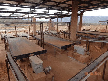
Figure 19. Example of gravity tables at a tin mine in Rwanda. Photo credit: Frances Wall.
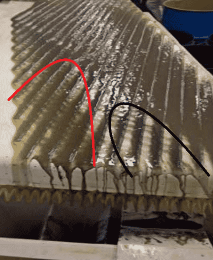
Figure 20. Shaking table in action. Note the black minerals on the right-hand side (magnetite) disassociating from the lighter brown minerals (monazite) on the left-hand side. Image from gravity test work on Eureka REE Carbonatite, Namibia.
FLOTATION (CHEMICAL BENEFICIATION)
Sometimes gravity methods may not be applicable in the recovery of some ore minerals from their host rocks, especially if the liberation size is very fine grained, and/or have complex mineral assemblages as the smaller particles are less amenable to physical separation techniques. Here froth flotation is an important concentration process and differentiates between particles by taking advantage of the surface chemistry of the particles.
In flotation, bubbles are introduced into a pulp of the crushed and ground ROM, with the addition of reagents, and the bubbles rise through the pulp. In the process, hydrophobic particles become bound to the surface of the bubbles. To enable these particles to attach, careful consideration of the chemistry of the pulp needs to be made. Changes to the charge of the particles’ surface and the acidity or alkalinity (pH) affects the chemisorption of collectors on the surface of the particles. The nature of the flotation reagents affects the operation of these processes. The most important chemical that is added is the collector. This chemical binds to the surface of the particles and is known as a surfactant. The frothers are another important chemical addition to the pulp as it enables stable bubbles to be formed. This is important as if the bubbles coalesce, minerals fall off their surface and cannot be recovered efficiently. Capex and opex, including reagent costs, are high for flotation plants but hopefully offset by improved recovery of target mineral – although flotation of many REE ROM typically achieve only around 30% recovery of target ores.
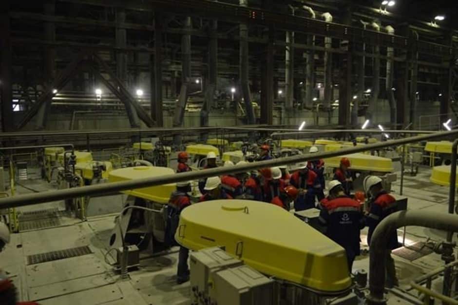
Figure 21. Flotation cells for apatite (phosphate production), Phosagro, Khibiny Apatite Mine, Kola Peninsula, Russia. Photo credit: Sam Broom-Fendley
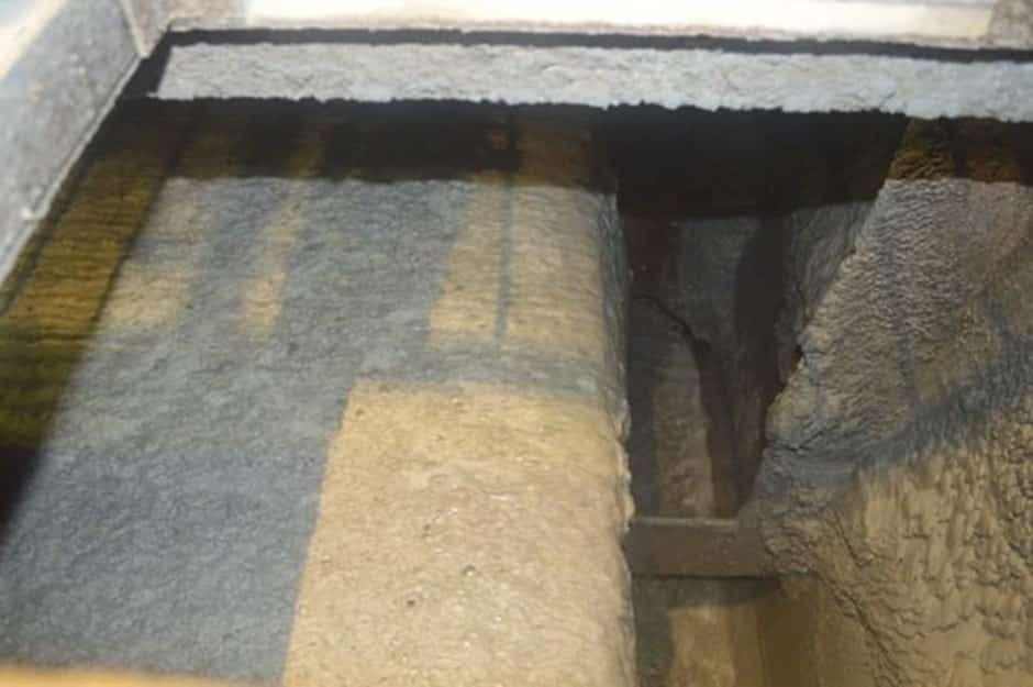
Figure 22. Froth flotation cells. Contained in the froth is the target apatite ore adhering to bubbles, Phosagro, Khibiny Apatite Mine, Kola Peninsula, Russia. Photo credit: Sam Broom-Fendley.
OTHER BENEFICIATION TECHNIQUES
Other important beneficiation technologies include:
Electrostatic separation – This process differentiates particles from each other by gravity and electrostatic attraction. It is commonly used for separating titanium ores and zircon from monazite and other minerals in heavy mineral sands.
Magnetic separation – This is where magnetically susceptible material is extracted from a mixture using a magnetic force. Low intensity magnetic separation is often used to remove iron minerals like magnetite from monazite concentrates. High intensity magnetic separation is used to remove mildly magnetic minerals (known as paramagnetic) like xenotime (the ore for heavy REEs) from concentrates.
Sensor-based sorting – Improved optical sensor technology has led to automated sorting being adopted in many mineral processing flow sheets. Sensors have been developed that use visible spectrum, near infrared, X-ray, and ultraviolet wavelengths to target particles. The technology can be coupled with electrical conductivity and magnetic susceptibility sensors, to control the mechanical separation of ore into two or more categories on an individual rock by rock basis. These sensors exploit properties such as electrical conductivity, magnetization, molecular structure and thermal conductivity. Sensor based sorting has found application in the processing of many commodities including nickel, gold, copper, coal, diamonds and even the REE mineral xenotime. But is expensive to install and run.
Revisiting the generalised flow sheet above, beyond the mineral processing (beneficiation) column, a mineral concentrate can be further separated in “value added” intermediate “cracking” stage, and eventual separation into individual REEs.
An example from an REE operation including all these steps is outlined in the following simplified flow-sheet:
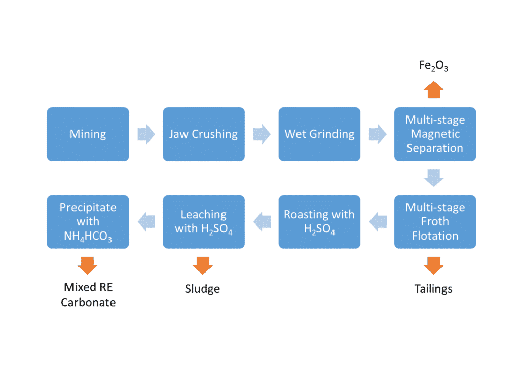
Figure 23. A simplified flowsheet for bastnäsite REE ore from a carbonatite deposit in China. From the chain of operations outlined in the previous two steps, note the initial jaw crushing and grinding (communition), followed by physical magnetic separation (where iron is rejected), followed by chemical flotation separation (where other waste minerals are removed).
The next stage of roasting, leaching and precipitation leads to what is known as the ‘cracking’ stage of the process. Cracking takes the concentrated bastnäsite REE ore and dissolves the fluorcarbonate portion and then a mixed rare earth carbonate product is precipitated. This mixed REE product needs further processing to separate out into the individual REE, such La and Nd for example, and we will look at that in the next step.
SOLVENT EXTRACTION
Refining of speciality metals can be complicated.
REE requires multi-stage solvent-extraction (SX) refining to separate the individual REEs – a multi-stage fractionation technique in some ways similar to how a range of hydrocarbon products, like kerosene, petrol and diesel are separated out from crude oil. So you have your mixed REE carbonate product from the previous cracking stage, what happens next?
SX utilises minor differences in solubility of the individual rare earth elements between aqueous and organic soluble phases. The aqueous phase is commonly a hydrochloric acid or, occasionally, nitric acid solution. The organic phase routinely based on organo-phosphate compounds.

Figure 24. Simplified schematic of a solvent extraction (SX) cell.
The process takes place in fully-enclosed mixer-settler tanks and reagents are recycled, with little environmental impact during normal operation. However, reagents required for the process are often expensive and specialised. Reagent manufacturing may pose environmental problems because these chemicals are often hazardous i.e. acidic. Operating costs are high because of the scale of infrastructure and the ongoing running costs. The process involves many tanks being operated in series with significant quantities of reagent and part-processed rare earths in the system at any given time.
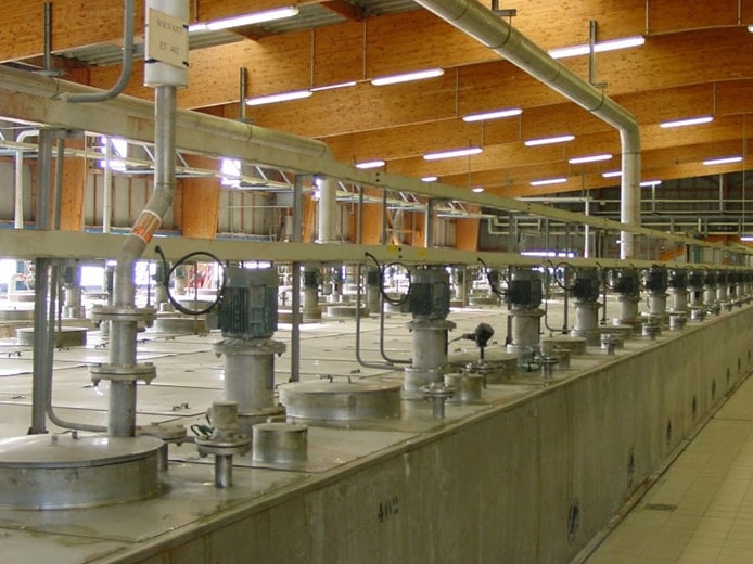
Figure 25. Commercial REE solvent extraction (SX) plant.
Most SX of REE in the World today takes place in China, but there are a few places outside of China with this capability. This is currently limited to Lynas’ LAMP plant in Malaysia, and the Silmet plant in Estonia. Due to the high capital costs involved in setting up an SX plant most mining companies do not have the capital to build them. It may require governmental intervention, or multi-governmental pooling of resources, to agree to guarantee the finance for such a plant.
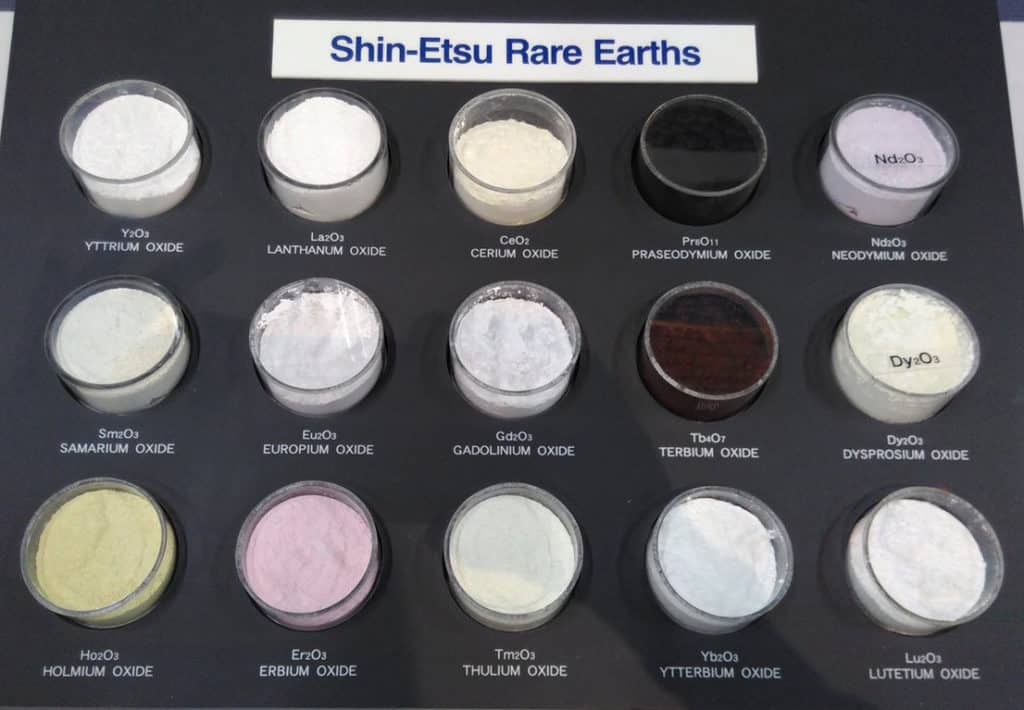
Figure 26. Separated rare earth oxides after solvent extraction. These oxide powders go for further refining into metals and other compounds, for example neodymium and praseodymium oxides will be reduced by fluorine salts and combined with iron and boron to make the high-strength NdFeB magnets that end up in our electric car motors and wind turbine generators. Photo credit: Frances Wall.
-
FUTURE REE MINES
There are many REE projects in the world today attempting to satisfy the diversification of supply and the increasing demand for these vital elements in our energy efficient future. These projects are situated all around the world targeting many of different deposit types as outlined above. In terms of economic viability, many have yet to prove themselves. Many promoters get stumped by mineral processing issues as highlighted above, or they require high-capex to reach production that no debt facility is prepared to front.
What should be the main metrics that determine whether a REE deposit is economically viable or not? In no particular order or weighting:
- An REE deposit of sufficient size that supports a multi-year mine-life
- A deposit of conventional REE ore minerals that are easily extractable in terms of minability, beneficiation and further processing. Preferably by virtue of being high-grade, mono-mineralic in a predictable and accessible ore-body.
- Logistical advantage. Access to infrastructure
- Situated within a friendly mining jurisdiction
- Producing a marketable product amenable to low-cost further processing i.e., by attaining global expressions of interest for product
- Ability to implement and satisfy internationally approved environmental, social and governance (ESG) standards
The Eureka project in Namibia, being developed by E-Tech Resources, goes a long way to fulfilling the requirements.

Figure 27. A simple mine to concentrate process for the Eureka project

